Editing CAD meshes
In OghmaNano, every 3D object has both a simple bounding shape and, optionally, a more detailed CAD mesh. By default, complex CAD meshes are disabled and each object is drawn using a generic box defined by its size in the Object editor. This section explains how to enable complex meshes and how to use the Mesh editor to configure different primitive shapes such as pyramids, tubes, and hollow tubes.
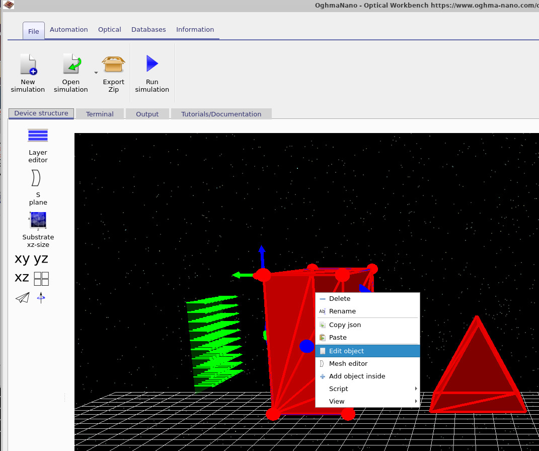
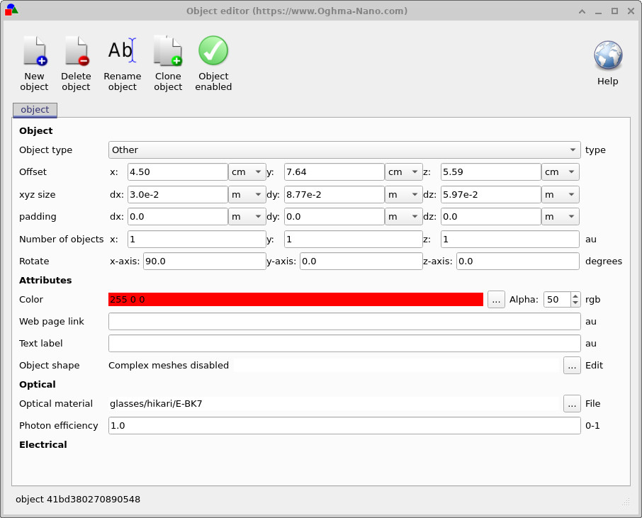
To edit an object, right-click it in the 3D view and choose Edit object, as shown in ??. This opens the Object editor window (??). Here, the xyz size fields (dx, dy, and dz) define the size of the object's default box-shaped representation. You can also change the object's position, rotation, colour, and the material it is made from.
At the bottom of the Object editor under Object shape, the text Complex meshes disabled indicates that no detailed CAD mesh is currently being used for this object. In this mode, the object is always drawn as a simple box, regardless of what optical material or other properties you choose.
Enabling the Mesh editor
To enable complex CAD meshes, click the Edit button (with three dots) next to Object shape in the Object editor. This opens the Mesh editor. When you first open it for an object, the mesh system is disabled, as illustrated in ??.
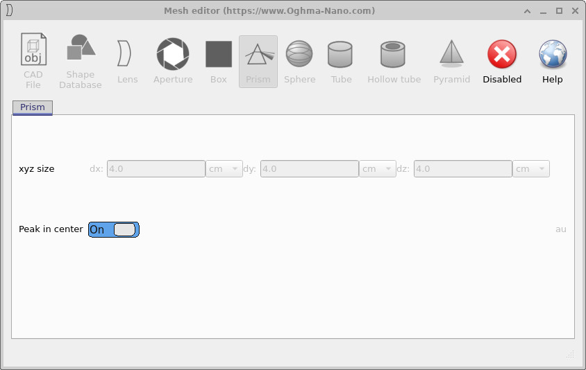
Click the Disabled button in the toolbar of the Mesh editor to turn complex meshes on. Once enabled, the editor switches to its default primitive shape, which is a pyramid. The configuration controls and the resulting mesh are discussed in more detail in the following sections, starting with the pyramid in ??.
Pyramid
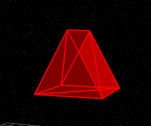
When complex meshes are first enabled for an object, the default primitive is a pyramid. The Mesh editor displays a toolbar of available primitives (box, prism, sphere, tube, hollow tube, pyramid, etc.) and a configuration panel for the active shape. For the pyramid, you can set its base radius, height, and number of sides. The pyramid mesh then replaces the simple box for that object in the 3D view.
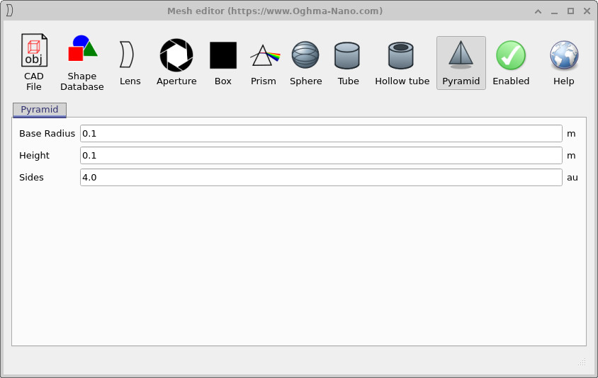
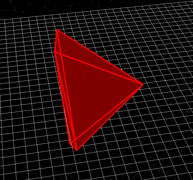
Adjusting the pyramid parameters in ?? immediately updates the mesh shown in the main 3D window (??). This makes it easy to fine-tune the overall dimensions before combining the object with other optics in your simulation.
Tube
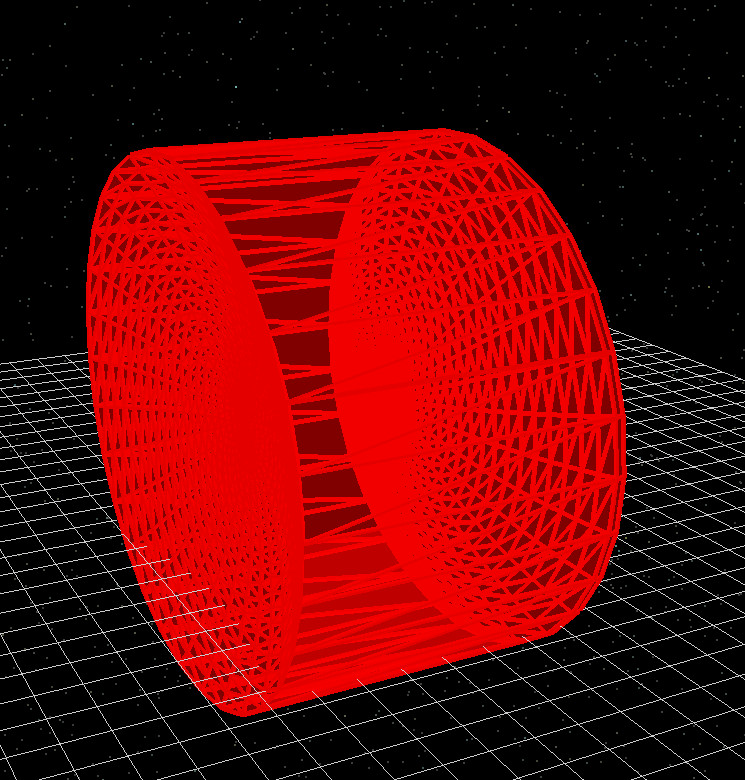
The Tube primitive creates a solid cylinder. This is useful for modelling rods, pillars, or waveguides. In the configuration panel you can set the overall radius, height, and the discretisation of the mesh via the number of rings and segments.
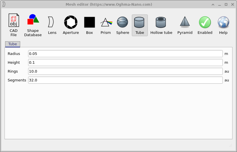
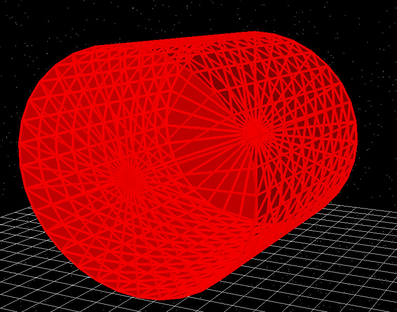
As with the pyramid, any changes you make in the tube configuration window (??) are reflected immediately in the rendered mesh (??). Increasing the number of rings and segments increases mesh density, which can improve geometric fidelity but may also increase ray-tracing time.
Hollow tube
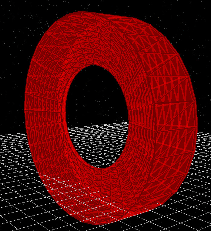
The Hollow tube primitive generates a cylindrical shell, with a user-defined inner and outer radius. This is useful for modelling pipes, hollow waveguides, or annular support structures. In addition to radius and height, you can set the number of rings and segments to control the triangulation of the mesh.
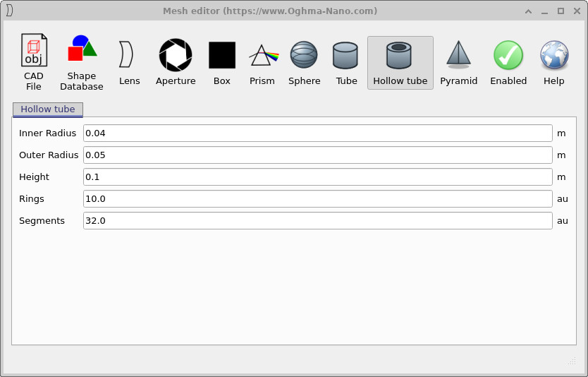
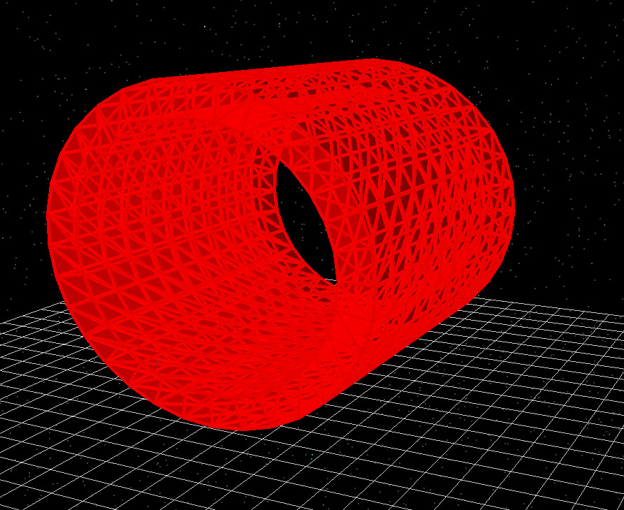
By adjusting the inner and outer radii in ??, you can move smoothly between a thin-walled shell and a nearly solid cylinder. As before, the mesh resolution is governed by the number of rings along the axis and the number of angular segments around the circumference (??).
Sphere
The Sphere primitive creates a triangulated spherical surface. In the configuration panel you can set the sphere Radius, along with the number of Rings (latitudinal divisions) and Segments (longitudinal divisions). Together these parameters control how finely the sphere is tessellated and therefore how smooth it appears in the 3D view.
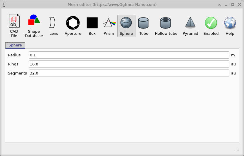
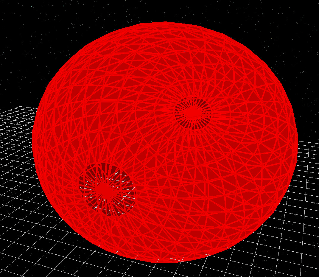
For many optical applications a moderate number of rings and segments is sufficient; increasing these values beyond what is visually smooth will only increase simulation time without improving accuracy. Use ?? and ?? as a guide when choosing suitable values.
Prism
The Prism primitive is designed for creating simple wedge-shaped or peaked structures. In the configuration panel you specify the overall xyz size of the prism (its dx, dy, and dz dimensions). The Peak in center option controls whether the peak of the prism is in the middle of the footprint or offset to one side.
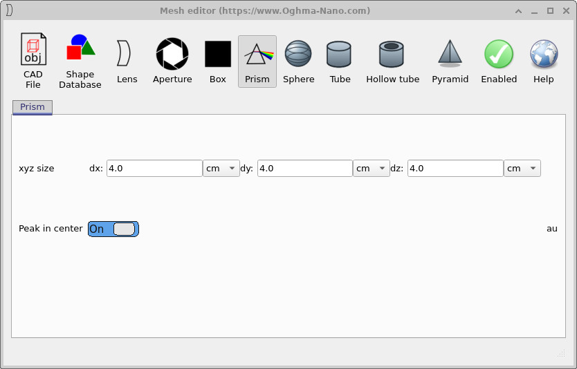
x, y, and z, and a switch to place the peak in the centre of the footprint.
Prisms are useful for building up more complex optical components, such as light-redirecting structures or simple beam deflectors. The relationship between the dx, dy, and dz values in ?? and the resulting geometry shown in ?? is direct, making it straightforward to design and tweak these shapes.
Box
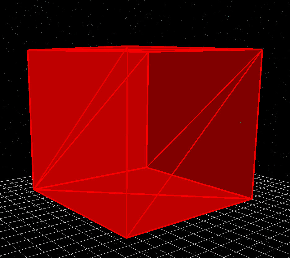
The Box primitive provides an explicit mesh-based version of the simple rectangular box used when complex meshes are disabled. You can specify the size of the box in the xyz size fields (dx, dy, dz). In most cases there is no practical advantage to using a box mesh instead of leaving the object as the default box shape, but the option is provided for completeness and for situations where you want all objects to use the mesh system consistently.
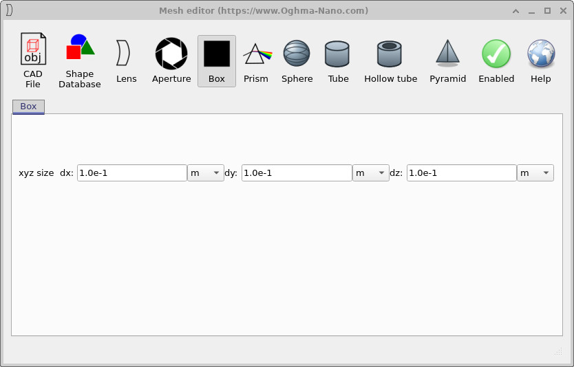
x, y, and z dimensions match those used for the default object box.
If you only need a simple rectangular object, you can normally leave complex meshes disabled and rely on the default box. However, the mesh-based box in ?? and ?? can be useful when you want consistent mesh-level control (for example, when exporting geometry or when combining with other mesh primitives).
Aperture
The Aperture primitive is intended for modelling optical stops and diaphragms. It creates a flat plate with a polygonal opening in the centre. In the configuration panel you specify the outer diameter d0, the inner diameter d1 (the clear aperture), and the number of Blades, which sets the number of sides of the polygonal opening.
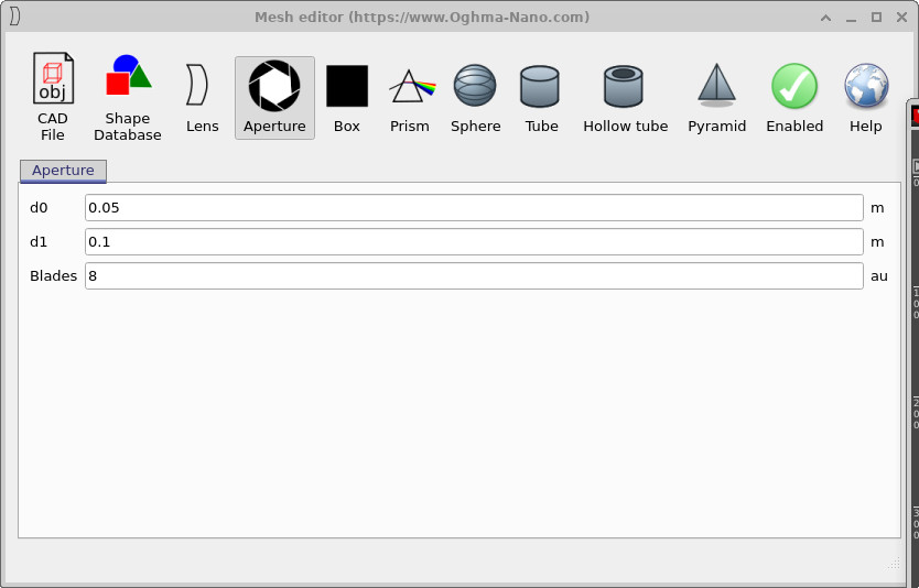
d0, inner opening d1, and the number of blades which sets the polygonal shape of the aperture.
In a typical optical model, the material of the aperture plate is set to an absorbing or metallic medium so that only light passing through the opening contributes to the simulation. By adjusting d0, d1, and the number of blades in ??, you can quickly prototype different stop sizes and shapes and immediately see the resulting geometry shown in ??.
Lens
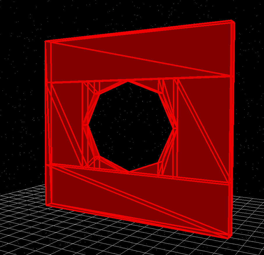
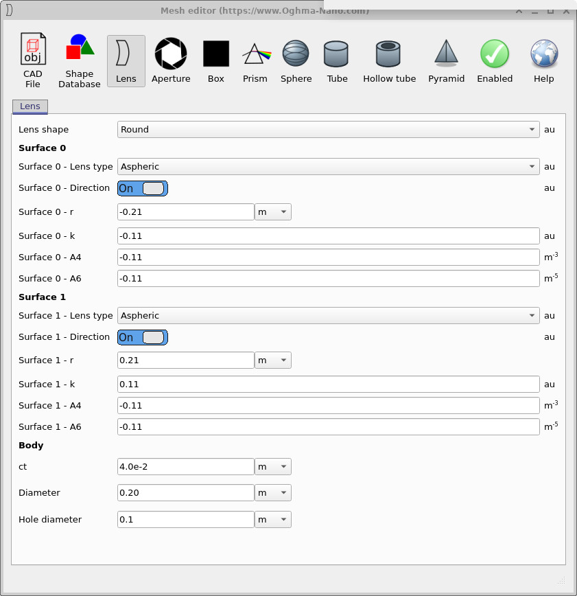
The Lens primitive in the Mesh Editor allows you to construct fully triangulated optical lenses. Lenses may be round or square, and each surface can take one of several shapes: plano (flat), spherical, parabolic, ellipsoid, hyperbolic, or aspheric. These options enable flexible modelling of optical elements for ray-tracing.
Each lens has two surfaces—Surface 0 and Surface 1—and each surface can be configured independently. Parameters include:
- Surface r — Radius of curvature (positive or negative depending on whether the surface is convex or concave).
- Surface k — Conic constant for non-spherical surfaces.
- Surface A4, A6, … — Higher-order aspheric coefficients.
- ct — Centre thickness of the lens body.
- Diameter — Physical diameter of the lens.
- Hole diameter — Size of an optional central hole.
The Lens Editor is powerful, but in most optical workflows lenses are more easily manipulated using the S-plane editor, described later. The Mesh Editor is mainly useful when you need explicit triangulated lens geometry for export or for visual debugging.
Together, the configuration examples in ??, ??, ??, and ?? demonstrate how the Lens Editor can construct a wide range of optical elements.
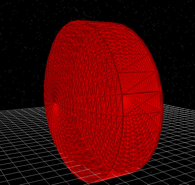
Shape database
The Shape Database option provides access to a library of pre-defined CAD meshes stored in OghmaNano’s own format. These shapes are not generated on the fly by the Mesh Editor; instead they are loaded directly from the internal database and can be reused across multiple simulations.
In addition to standard library shapes, you can also import flat images—such as AFM height maps—into the Shape Database and convert them into 3D objects. This makes it a convenient place to keep frequently used geometries together, whether they originate from measurements, external CAD tools, or previous projects.
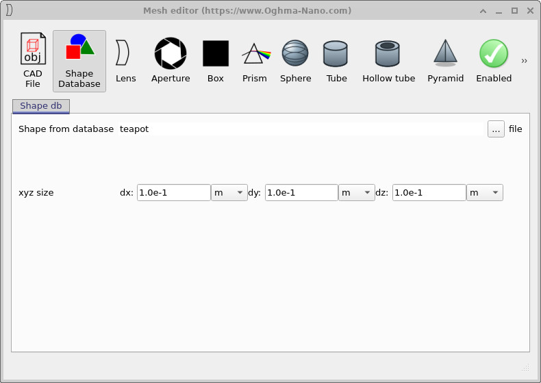
teapot) is selected from the
internal library and scaled using the xyz size fields.
Once a shape has been chosen in ??, it behaves like any other mesh primitive: it is attached to the current object and participates fully in the ray-tracing simulation.
Importing CAD files
Instead of first adding shapes to the internal database, it is also possible to attach meshes directly from external CAD files using the CAD File option. This is useful when you already have a model stored on disk and simply want to bring it into an OghmaNano simulation.
At present, the importer supports standard Wavefront OBJ files. Other, non-standard or proprietary formats are not accepted, so if your geometry is stored in a different format it should be exported as a Wavefront OBJ mesh first.
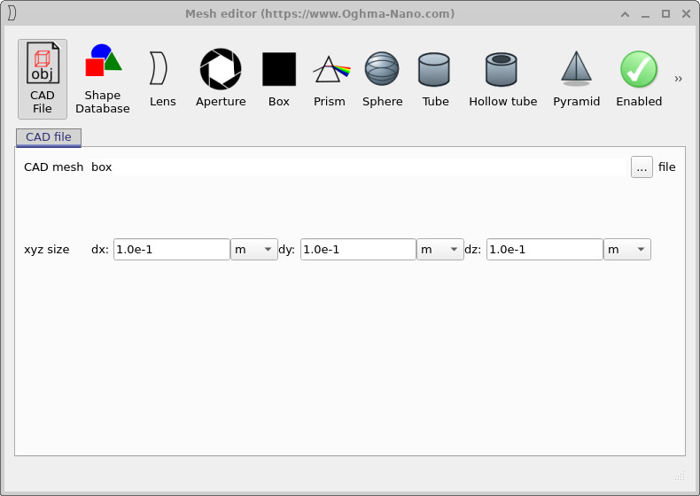
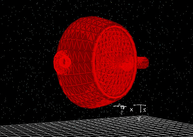
The example in ?? and ?? shows how an external CAD model can be brought into OghmaNano and combined with other optical components in the scene.